What is MIM?
In order to explain what MIM is, it is prudent to first see why we need MIM and DE in the Mining industry.
The objectives are to deliver the Mining projects to the,
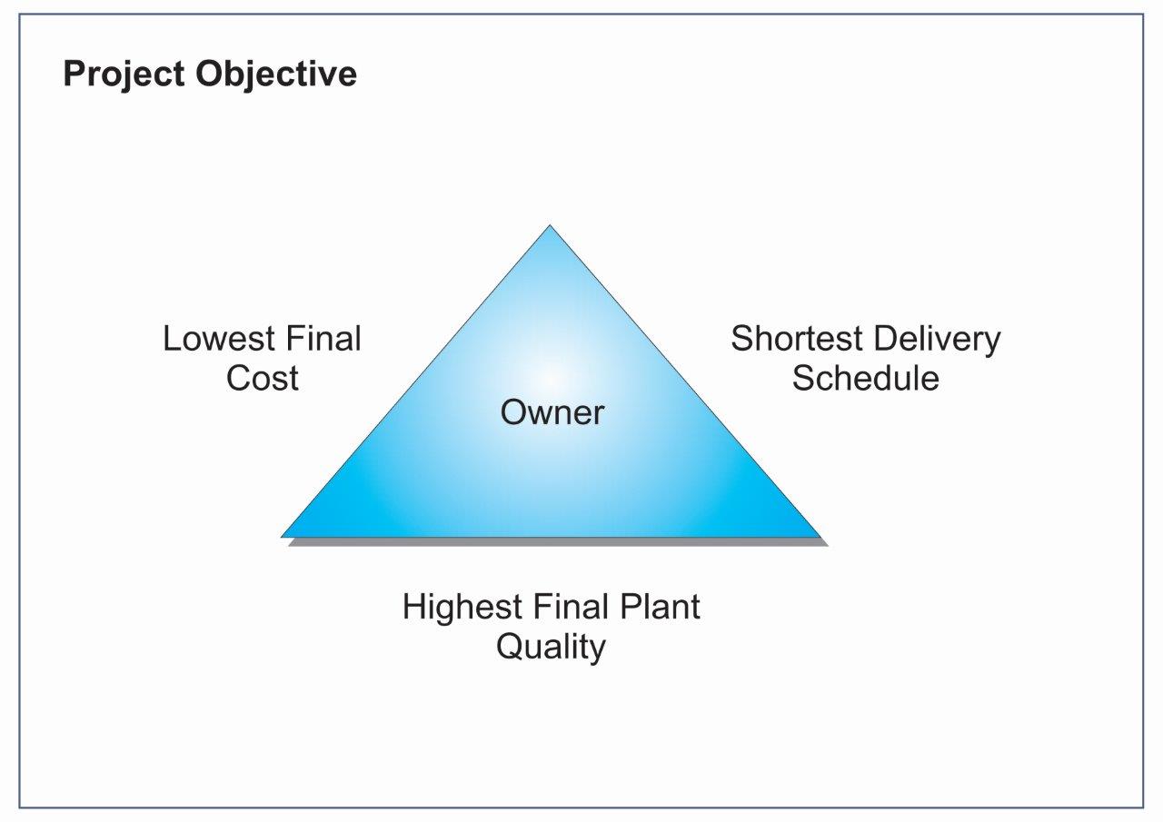
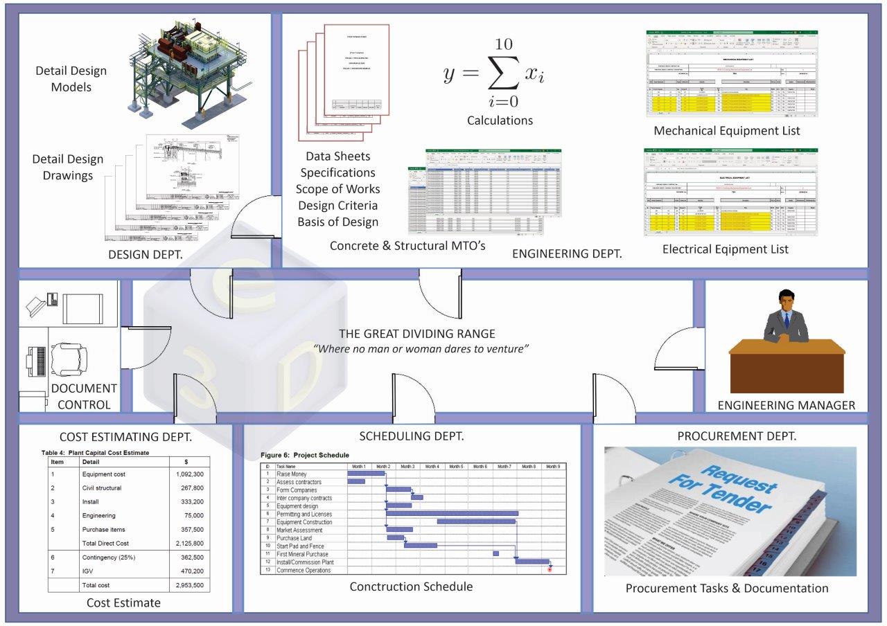
What happens then and what we deliver,
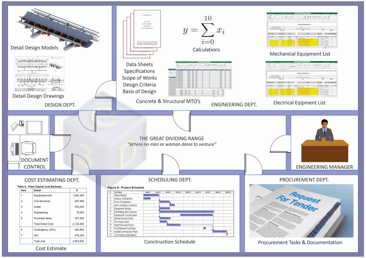
Ok, the above image might be a slight exaggeration and a bit simplistic, but I am sure we can all relate to being on a project like this at least once (or twice).
The take home from the above image is that every department is flat out deriving their own datasets to do the tasks they need to deliver the project.
For instance,
- The Designers - are busy creating design models and producing drawings from the design models. The 3D models are only used for visuals, drawings creation, and interdisciplinary clash checks; typically, no other information is derived from the 3D models.
- The Mechanical Engineers - are busy manually counting the mechanical equipment either from the drawings or looking at the 3D models and entering each line item into the Mechanical Equipment List spreadsheet.
- The Electrical Engineers - are busy manually counting the electrical items either from the drawings or looking at the 3D models and entering each line item into the Electrical Equipment List spreadsheet.
- The Structural Engineers - are busy creating the concrete and structural MTO's from Space Gass or manually from the drawings/models (scale rule and calculator). Note, the Space Gass models are not accurate for MTO's as these models' are for the purpose of performing Structural Analysis and do not include beam cutouts, connections, and other plate work.
- No Bolt Lists - for some reason, no bolts are shown in the models, and no bolt lists are included in the detailed design drawings. Subsequently, these are now either assumed quantities or not included in the Cost Estimates. Bolt lists were phased out of the detailed design deliverables in 2004 (approximately). Bolts are now left to the Shop Detailers to determine which normally happens after the completion of the cost estimates and schedules.
- The Cost Estimators - are busy scouring the drawings and 3D models and manually adding line items to their cost estimates. Due to time pressures, sometimes assumptions are made as it is too time-consuming to create a highly detailed list of components from the drawings or looking at the 3D models.
- The Schedulers - are busy scouring the drawings and 3D models and manually adding line items to their schedules. Due to time pressures, sometimes assumptions are made as it is too time-consuming to create highly detailed list of components from the drawings or models.
- The Procurement team - are busy scouring the drawings, looking at the 3D models, cost estimates, schedules, MTO's, specifications, and equipment lists to determine the packages required for procurement. Note, please correct if this is not the methodology used for procurement.
During this process, several disciplines are creating duplications of project data (which may not be the same in each dataset), assumptions are made and human errors occur, which carry thru to the Construction Phase. A project's success is directly related to the detail and quality of information supplied at the Engineering and Design phase. "It's all about the information."
Missinformation and/or lack of information from the Engineering and Design deliverables is well-documented to be the major root cause for Construction cost blowouts and schedule delays.
Keep reading to see how the e3D MIM CAD Build removes this duplication of data, reduces the 3D modeling, MTO's, Equipment Lists, Cost Estimating, Scheduling, and Procurement effort by more than 25%, increases the accuracy of the delivered project data, and minimizes project risk (proven on projects completed).
No CAD System specific for designing mining projects is available in the marketplace.
You cannot simply purchase a CAD system, be it 2D, 3D, or 3D BIM-enabled, and start producing designs for mining projects. Any CAD system adopted will need to be re-configured, the base data changed or added to enable the creation of mining related components and the required outputs from those components. The re-configuration of this data is done in what is called “workspaces”.
What are workspaces?
Definition: The tools within the application are considered as the application and are fixed items that are required to use the application. The workspace controls the modeling environment, modeling workflow, and data to be used in the modeling process and comprises many configuration variables, datasets, and systems built upon systems.
In our case, we have taken a very powerful BIM (Building Information Modeling) CAD system from the Architectural, Engineering & Construction (AEC) industry and reconfigured the workspace to be specific for the Mining industry. The reconfigured BIM CAD system from here on shall be referred to as “MIM”.
What is MIM?
Definition: Mining Information Modelling (MIM) is a 3D CAD application for creating and managing all 3D component related mining project information. The 3D models created by using the CAD application contain the digital description of each component as non-graphical metadata. The metadata is instantly associated with the related 3D graphical object and applies to every item modeled within the project. It provides subject-related data for every component in the project.
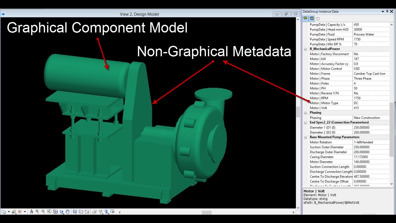
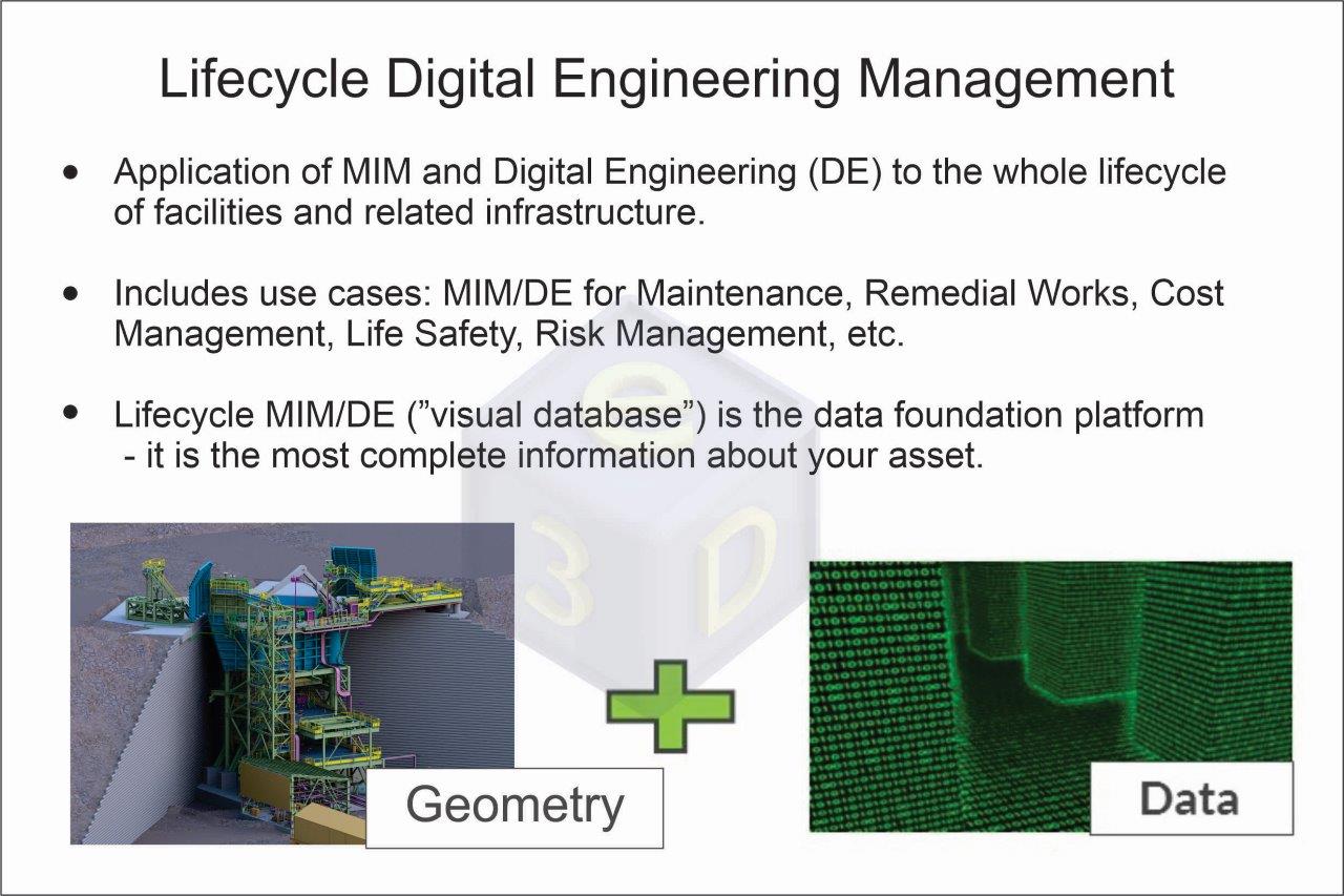
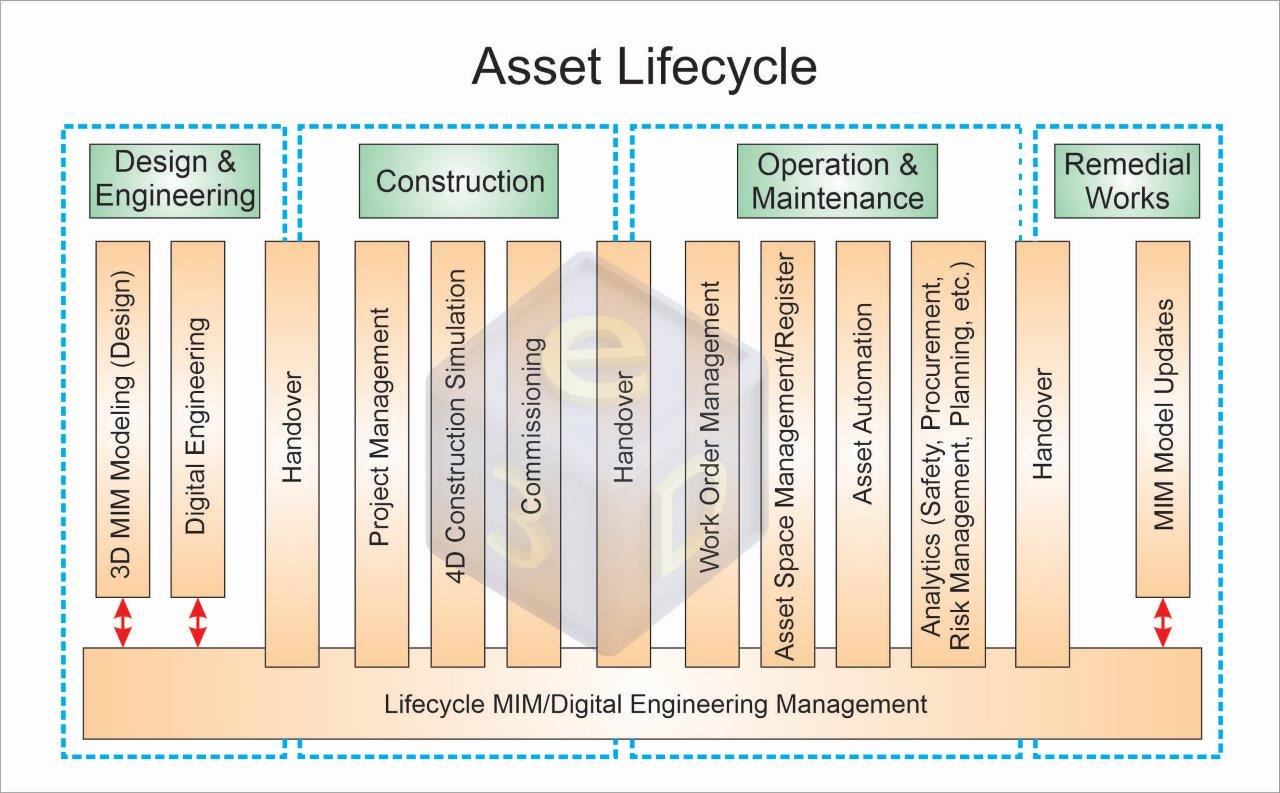
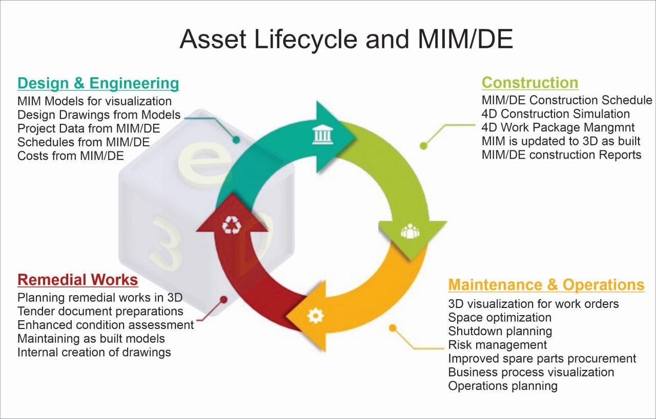
Purpose: MIM's purpose is to utilize the data-rich 3D models to provide clash detection, 2D drawing deliverables, very accurate and consistent project data as the single source of truth for the project. The data generated from the 3D models and the 3D models are utilized for Digital Engineering in the Engineering and Design phase. The data-rich 3D models created by the MIM CAD application are used for concept design, detail design, construction, asset management, and demolition, which covers the entire lifecycle of the built asset.
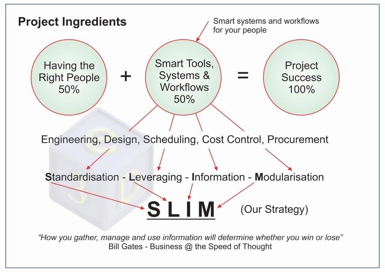
E3D’s strategy is a holistic top-down and bottom-up approach that produces project data from the 3D models to provide the foundation for enabling Digital Engineering data use in all other project activities. We call it the "SLIM" strategy.
Mining projects vary from small brownfields to large mega-projects; the scope can vary from Wet Plans, Dry Plants, Process Plants, Airports, Camp and Mine Facilities, Bridges, Tailings Dams, Rail, Marine Ports, etc. The amount of data captured in a mining project can be so extensive that it is no longer helpful unless it can relate to a specific facility and subject matter within that facility. We have added classification and commodity systems that are automatically built into every component in our CAD Build. This not only tells the story of how each component relates to the project but also allows you to sort and filter the data by Entity, Item, Discipline, Part, Sub-Part, and Commodity.
It is the structured data that is the foundation of e3D's MIM CAD Build. Additional data fields are provided for discipline-specific Vendor details and project-specific data (every client uses different commodity codes). The data fields are the glue that binds the data to all other project activities like MTO's, Equipment Lists, Cost Estimating, Scheduling, 4D Construction Simulations, and Procurement, drastically reducing the effort required to create these items. Now add substantial prepopulated Vendor and Standards 3D model libraries that have been built with all this data already in them, and you have a "Super MIM" system.
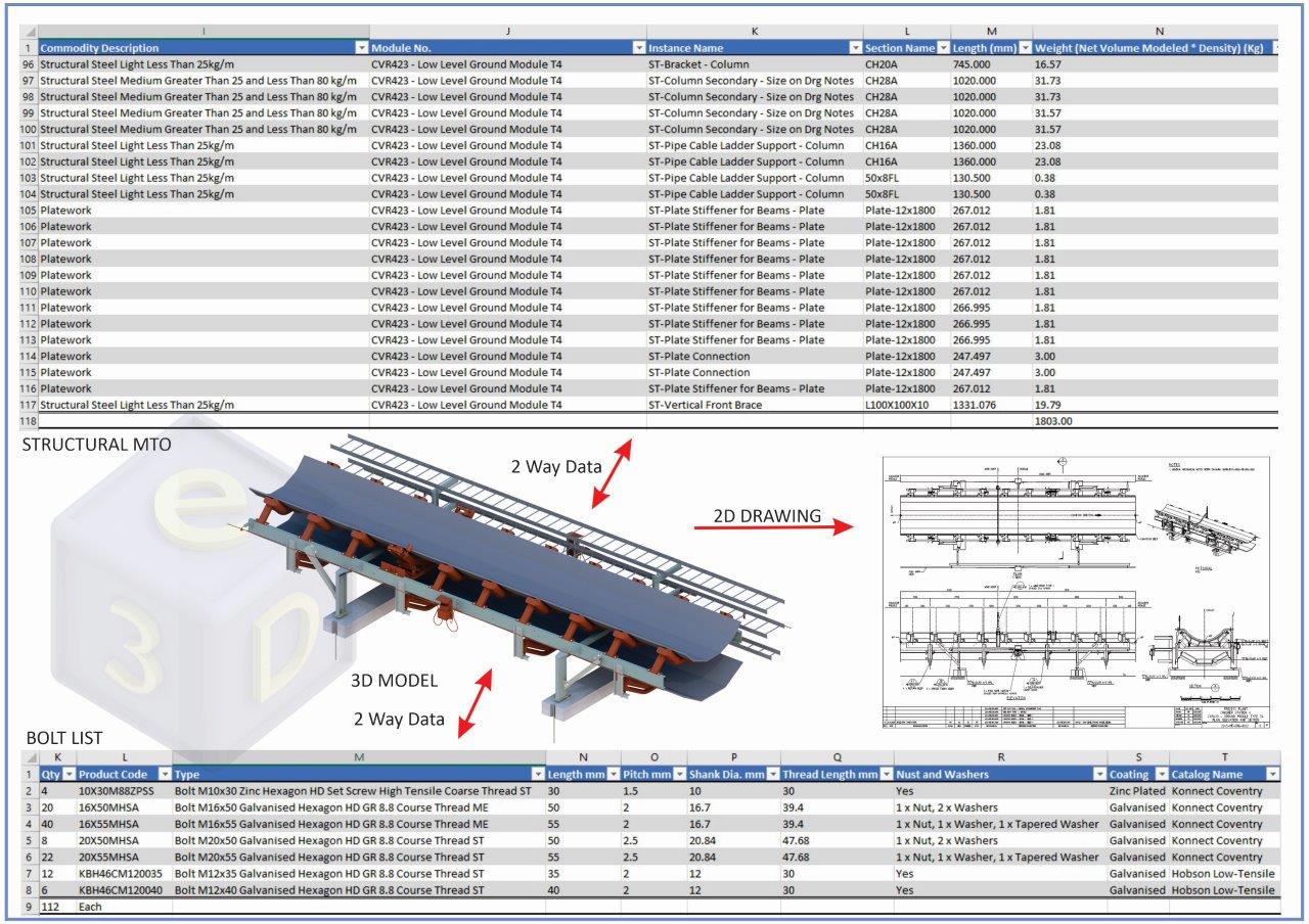
Structural MTO and Bolt List from Conveyor Ground Module 3D model. It is diffult to display the entire dataset here, request a demonstration to see everything.
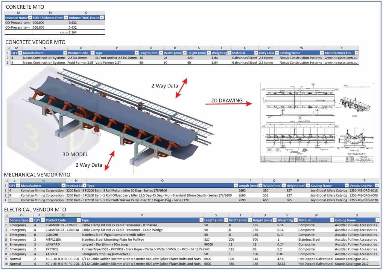
Concrete MTO, Concrete Vendor MTOm Mechanical Vendor MTO and Electrical Vendor MTO from Conveyor Ground Module 3D model.
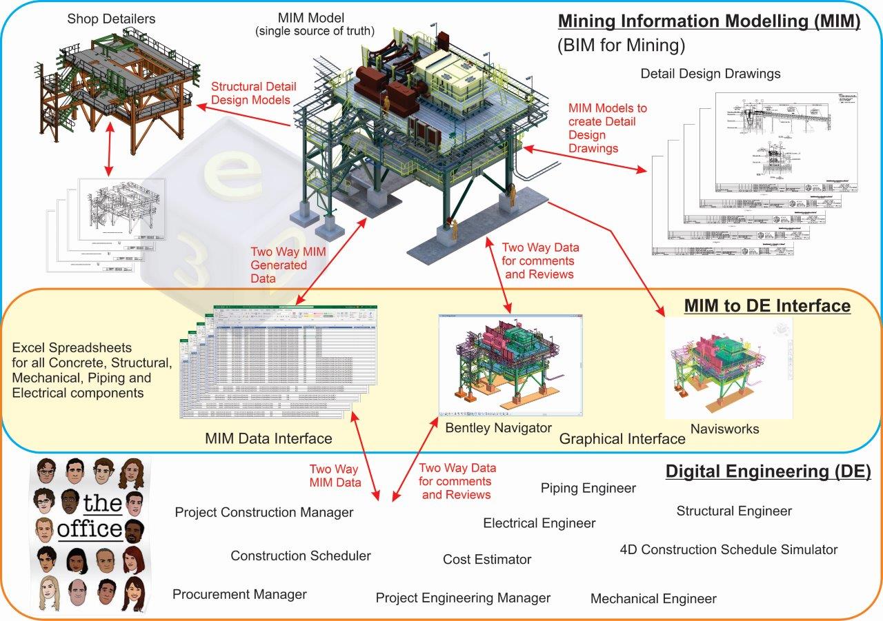
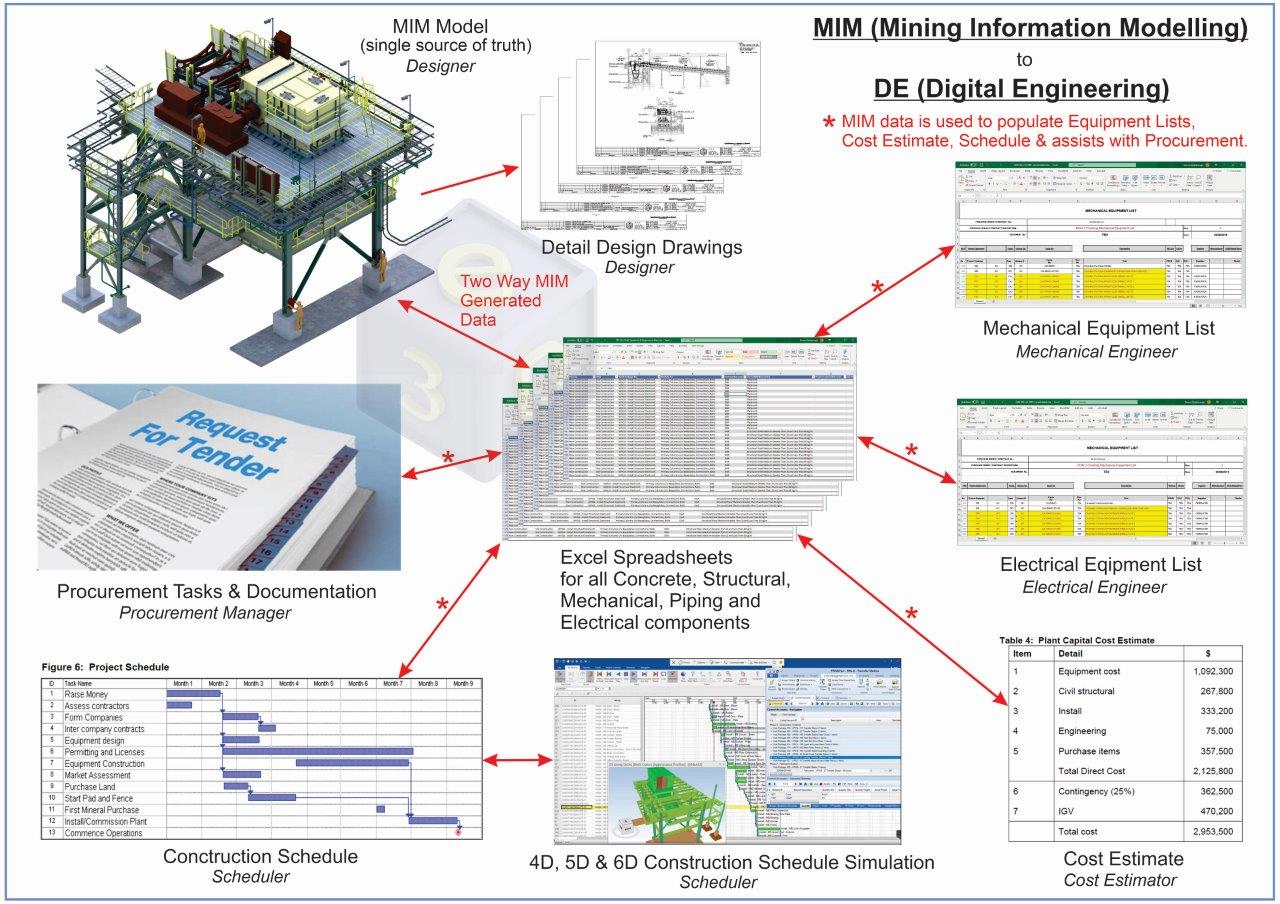
3D models created using e3D's MIM CAD Build generate structured data for the projects. Digital Engineering (DE) uses those models and structured data for all project activities, which is again used for the asset's entire life cycle.
MIM to DE is collaborative by its nature and requires inputs to and from your Engineers, Cost Estimators, Schedulers, 4D Construction Simulators, and Procurement.
We go from doing Mining projects like this.
To doing projects using the single source of truth for highly accurate, data-rich projects to reduce risks and remove duplication of effort. This adds maximum value to your clients by enabling your 3D models and MIM data to be utilzed throughout the asset's entire life cycle.
"Less Effort - Higher Quality - Faster"
No BIM-enabled CAD system exists for specifically designing Mining projects.
It makes sense to take a highly developed and powerful BIM-enabled CAD system from the AEC industry and adapt it to the Mining industry. Both the AEC and the Mining industries use the same tools and work as disciplines, i.e., Concrete, Structural, Mechanical, Piping, and Electrical. Although the AEC industry uses the same tools and disciplines as the Mining industry, they both work very differently. The underlying BIM philosophies and workflows used in the AEC industry can be greatly simplified for the Mining industry, hence, MIM to Digital Engineering (Mining) rather than the all-encompassing BIM (AEC).
There are many BIM CAD software packages from the AEC industry to choose from. Each will require extensive (& expensive), time-consuming reconfiguration and data to make them suitable for designing Mining projects.
Here are some of the more popular BIM-enabled CAD systems,
- AECOsim (OpenBuildings)
- Revit
- Inventor
- Solidworks
- ArchiCad
- Tekla (Shop Detailing CAD System)
- Advance Steel (Shop Detailing CAD System)
- ProSteel (Shop Detailing CAD System)
Here are the reasons why we chose AECOsim for specifically designing Mining projects,
- Able to model in real-world coordinates - Some Mining projects are huge and can have their facilities and conveyors spread over many kilometers. These facilities and conveyors must align perfectly, it can be very costly to fix any misalignments. 3D model designs must be in real-world coordinates to have the ability to click on any component or work point to find its exact Northing, Easting, and RL, anything else poses too high a risk.
- Large models, small file size - The DGN model and drawing files are approx. 1/5 the size of models and drawings created by other BIM packages. This helps a lot for file management, server synching, and other project activities when the Design office is spread out in different geographical locations.
- Stable platform - AECOsim has been used to design some of the largest projects in the world, one example being the design and construction of a $3 billion, 7-million-square-foot terminal building for the Abu Dhabi International Airport. It is ideal for small, medium, large to mega-mining projects. It doesn't fall over when the models get large and complex, the software is designed for this purpose.
- All disciplines work in one 3D modeling environment - All disciplines work in one 3D modeling environment and have access to the same discipline-specific tools. This allows each discipline to work in parallel and design their specific components while seeing the other discipline's components, creating a live and interactive modeling environment. Having all of the tools of the disciplines available to all Designers provides the flexibility of multi-discipline Designers to model components that are required for the project and not be pigeon-holed into one discipline.
- Built-in clash detection tools - AECOsim comes with comprehensive clash detection tools. However, due to all the disciplines working in the one 3D model environment and every discipline seeing each-others design models, it is not widely used other than as a final check for any clashes that may have been missed by the design team.
- BIM models and data exports to IFC and Cobie -IFC and Cobie export tools are well developed and contained within AECOsim. IFC exports are beneficial for exporting the structural models into Shop Detailing packages. Cobie is the common language for importing the AECOsim 3D models and associated data into BIM-enabled Facility Asset Management (FM) applications.
- High-quality images and animations - Almost photo-realistic rendering and animation creation tools are built in to the AECOsim toolset. While the high-quality images are great for marketing and can demonstrate a design, the animations are handy for crane studies. The animations can also demonstrate how equipment can be removed and re-installed for maintenance (also great for marketing). AECOsim is 4D capable, but the 4D tools are fairly difficult and time-consuming to use; you are better off having a separate package specifically for 4D construction simulations.
- Configuable workspaces and datasets - Bentley has always recognized that each company and industry can work in different ways. For this reason, Bentley provides flexible open-source workspaces and datasets that are configurable by the company using their CAD software. This is why it enables the adoption of their BIM-enabled CAD system to work so well for designing Mining projects. The backside to this is that it requires a substantial amount of work (& time) and requires very in-depth knowledge of AECOsim, the Mining industry, and how Mining projects are done in the industry.
- The big 4 Miners prefer DGN models and drawings - BHP require all drawing deliverables in the native DGN format that complies with BHP CAD Standards. FMG, Riotinto, and Roy Hill request all of the native drawing and model files to be in DGN format, but while it is not preferred have been known to accept other CAD formats.
- Bang for your buck - AECOsim is extremely powerful and relatively inexpensive for what it can do, it has to stay that way to remain competitive with its rivals in the AEC industry. Finally, a win for us.
- Many ways to report the MIM data - Firstly, the data is two way (bi-directional). Secondly, the data can be reported in Excel, as a text file, a CSV file, or an XML file ready for your own company database. Thirdly, you control exactly what data you want to be reported, and in the case of Excel you can set up your own company Excel schedules (with your logo's, etc.) that the system will report to.
- One BIM CAD system does it all - No additional 3rd party software or plugins are required to do clash detection, manage the data or create stunning visualizations; it does it all from within AECOsim.
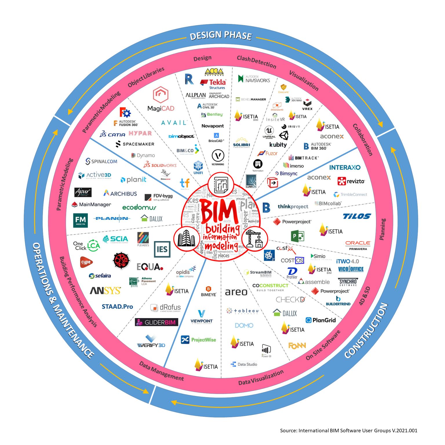
Here are the most commonly used software applications, 3rd party apps, and plugins used in the AEC industry, all under the one BIM acronym.
Here is the MIM to Digital Engineering software for the Mining industry (using AECOsim as the MIM application).
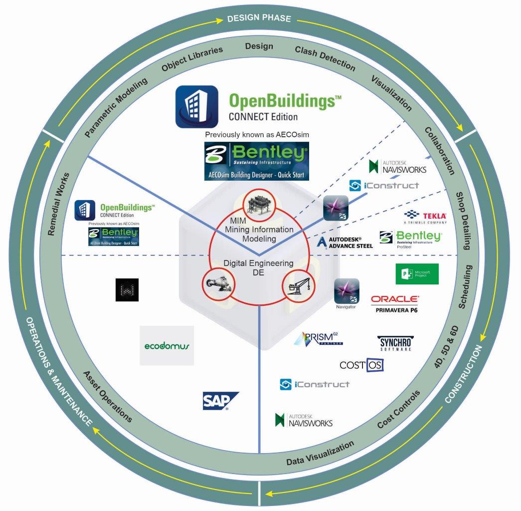
It is much more efficient and cost-effective to be "Master of one BIM CAD system", one license, one workspace set up, one CAD system to build libraries for, and the re-use of legacy project models. Rather than have many CAD systems and be "Master of none", so many additional licenses to pay for, 3rd party apps and plugins to deal with, workspaces to set up, other libraries to create, redundant legacy project models (done in different CAD systems).

